 |
Next: A Software Package for Automatic Reduction of ISOPHOT Calibration Data
Up: Data Analysis Applications
Previous: Recent Developments in Experimental AIPS
Table of Contents -- Index -- PS reprint -- PDF reprint
H. He, J. McDowell and M. Conroy
Harvard-Smithsonian Center for Astrophysics
60 Garden
Street, MS 81
Cambridge, MA 02138, Email:hhe@cfa.harvard.edu
The work of He (1997) established a preliminary framework for the pixlib system, including the parameter-interface data I/O structure, matrix calculation algorithm, and coordinate transformation threading baselines. Since then, the library has undergone thorough re-organization and expansion to meet the AXAF on-going requirements of both ground calibration and flight observation. At the time of writing, the library is about 95% completed with approximate 6000 source lines of codes. It was successfully integrated and built during the XRCF calibration phase.
In this paper, we will highlight the system design and architecture of the library, complementary to the early work, and describe the system configuration in terms of user application. The complexities of coordinate transformation at XRCF and the resolutions will be discussed.
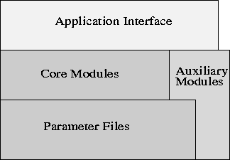
The building blocks of the Pixlib library are three sub-systems, core, auxiliary, and application interface (API), and the foundation of the library is built with the parameter-interface structure. Figure 1 sketchs the architecture of the library.
 |
As discussed in He (1997), the design of pixlib is modular to allow system expandibility, easy maintenance and simple ways to incorporate new scientific knowledge. The core sub-system, which includes 8 modules (see Figure 2 for details), builds the ASC coordinate frameworks of grating, FAM motion, sky aspect offsets, telemetry (raw) reads, detector-chip tiling, and coordinate transformation among chip pixels and celestial angles. Because of the common needs of generic data sources, handy utilities, module-to-module communication, etc., the library is supported with a 4-module auxiliary sub-system, as shown below.
      pix_errstatus.c    -- error handling
      pix_utils.c        -- utility functions
      pix_common.c       -- common data sources to all modules
      pixlib_hiden.c     -- internal configuration, bookkeeping
The upper-level interface of the library is implemented in the module
pixlib.c, which distributes functions between the lower-level
modules. pixlib.c, in large part, provides setup
functions for system configuration, and other API functions are
implemented locally without the need for cross-module function calls.
All the API functions are identified by the ``pix_'' prefix.
The data in-stream of the parameter-interface approach
simplifies system configuration and data readability. The number and
organization of those data files have
remained almost same as described in He (1997) with few updates.
pix_pixel_plane.par, substituting
the original pix_size_cnter.par,
groups 2-D pixel system parameters of focal plane, tiled detector, grating
dispersion together; pix_grating.par is added
to define dispersion period and angle of grating arms.
pix_coords.par,
handles the static configuration and the user can set values for the
following parameters.
  flength = Telescope focal length in mm
 aimpnt   = Name of aim point  of detector
    fpsys = Focal Plane pixel system
  tdetsys = Tile Detector pixel system
   gdpsys = Grating Dispersion pixel system
  grating = Grating arm
    align = FAM    misalignment angle in degrees(pitch, yaw, roll)
   mirror = mirror misalignment angle in degrees(pitch, yaw, roll)
In the course of the system initiation, executed through
pix_init_pixlib(),
internal functions lookup the parameter table to parse the
information down to relevant modules, which are then
configured accordingly.
An alternative way to configure the system is to make function,
``pix_set_*", calls in application program following
the initiation. pix_set_flength(int), for instance, is
equivalent to the pset ``flength'' for pix_coords.par, and
pix_set_fpsys(int) to the pset ``fpsys'', to name a few.
The consequence of those calls is
to override the static configuration which is the system defaults.
Coordinate transformations at XRCF need to be carefully handled when the FAM feet move and the HXDS stage dithers. In the default, boresight configuration the FAM axes are parallel to the XRCF (and Local Science Instrument, LSI) axes, but they may undergo some movements in addition to the HXDS stage dithering and possible mirror mount movement. Therefore, those effects, as listed below, must be accounted for before coordinate transformations between focal plane and LSI system are made:
The following two functions, in addition to other generic configurations, effectively supply the system configuration for coordinate transformation at XRCF. The routine
   pix_set_mirror (double hpy[2],       /* in degrees */
                   double stage[3],     /* in mm      */
                   double stage_ang[3]) /* in degrees */
corrects misalignment from the mirror axis
by measuring its displacement from the boresight configuration of the
default FAM frame (stage_ang)
for a given mirror position (hpy) in mirror nodal coordinate system.
The hpy is measured in HRMA pitch and yaw axes, and
the HXDS stage position (stage) monitored relative to the default FAM
reference point. The routine
   pix_set_align(
       double mir_align[3], /* (yaw, pitch, roll), in degrees */
       double stg_align[3]) /* (yaw, pitch, roll), in degrees */
serves to assess
mir_align) relative to XRCF axes are measured in
the given yaw-pitch-roll Euler angles in the mirror nodal coordinate,
and
stg_align) relative to XRCF axes are corrected
in terms of yaw-pitch-roll Euler angles in the default FAM frame.
The system configuration above was successfully applied to and integrated into ASC data analysis during the X-ray calibration.
We gratefully acknowledge many fruitful discussions with ASC members. This project is supported from the AXAF Science Center (NAS8-39073).
McDowell, J., ASC Coordinates, Revision 4.1, 1997, SAO/ASCDS.
He, H., McDowell, J., & Conroy, M., 1997, in Astronomical Data Analysis Software and Systems VI, ASP Conf. Ser., Vol. 125, eds. Gareth Hunt and H. E. Payne (San Francisco, ASP), 473.
Next: A Software Package for Automatic Reduction of ISOPHOT Calibration Data
Up: Data Analysis Applications
Previous: Recent Developments in Experimental AIPS
Table of Contents -- Index -- PS reprint -- PDF reprint